5 METER-LONG
PANTOGRAPHIC GIMBAL
 Highway project
 Southeastern Europe
 EJMA
EJMA
Since 1994 Belman has been known in the market for its customized solutions, engineering capabilities, and passion for finding the right solution for the client. In some situations, the client and the application using the Expansion Joint is having so demanding parameters and/or limitations in options – that a highly customized Expansion Joint is needed. In these situations, the client needs to turn to experts on this field. Belman fusion excellence in engineering, craftmanship and years of experience within Expansion Joints into solutions that meet even the most demanding needs. This is what Belman do finest, always pushing boundaries for the impossible, but we gladly do it to help the client achieve success in his/her projects. This case story is just another example of a remarkable Expansion Joint that demonstrates Belman’s ability to create impressive and innovative Expansion joint solutions.
The need of the client
For a highway project, in South-Eastern Europe, the client needed a top engineered Expansion Joint solution as the application resulted in movement as big as 450 mm dilatation (in total 900 mm). The pipeline was DN 300 and the pressure required a design pressure for the Expansion Joint of 40 barg. This engineering challenge Belman took and helped the client gain a super cool Expansion Joint design that simply had it all in one piece.
The Belman solution
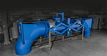
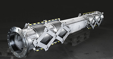
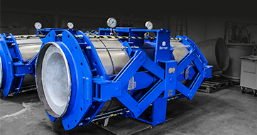
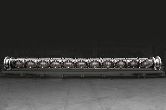
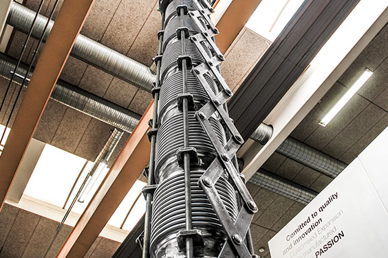
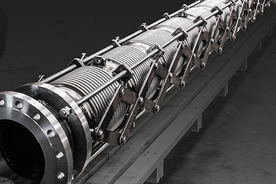
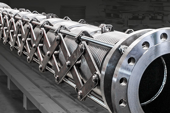
Actually for this project Belman has gone above and beyond and engineered a true masterpiece – to ensure the perfect solution for the client – the result was a 5-meter-long Pantographic Expansion Joint. As Belman was not limited in built-in length the Expansion Joint was super optimized, but however ended up in 5-meter built in length. To keep the 40 bars pressure and take up 450 mm axial movement (900 mm range) Belman designed the Expansion Joint with 11 bellows in a line, as several bellows in sequence allow the absorption of very large movements – in this case the +/-450 mm axial movement. To avoid premature wearing out of some bellows a pantographic linkage design was chosen, as this device ensure uniform movement of each bellow by distributing the total amount of axial movement and dividing it equally to each bellow within the Expansion Joint. The very long Pantographic Gimbal Expansion Joint was tested at 60 barg pressure. To verify the design Finite Element Analysis (FEA) was used, among others also to check the inner sleeve. Furthermore, a 3D drawing as well as detailed drawings of the parts in the Expansion Joint was provided to the client.
DESIGN FEATURES
Design parameters of the 5 meter-long Pantographic Gimbal Expansion Joint
Quantity: 1 pcs. • Dimension: DN 300 • Built-in length: 5400 mm • Design temperature: -35°C/+50°C • Design pressure: 40 barG • Media: – • AX: +/-450 mm (range: 900 mm) • Bellows: 1.4541 (AISI 321) • Flanges: 1.0460 (C 22.8 I) • Design code: EJMA
CLIENT BENEFIT
- Benefit from the considerable know-how of an experienced manufacturer
- Engineered to meet and work in all operating parameters
- Reliability of the Expansion Joint designed to work under the operating parameters
- Sound and cost-efficient Expansion Joint solution that ensures a smooth and safe operation
RELATED INFORMATION
TECHNICAL information
- Technical information on Pantographic Gimbal Expansion Joints
is available in the Expansion Joint Catalogue
page 377
REFERENCES
Cummins • Weinberger • International Silencers •
Norcem • Power Machines • Caterpillar • Bronswerk •
WMF Group • Lee Tunnel • Cementa • ESS • Rolls Royce •
Deutsche Bahn • Saline Water Conversion Cooporation (SWCC) • University of Oxford •
Egger Technologies • Shell • FLSmidth


